
PID CONTROL of the pressure system
The PI parameters were obtained by using the Pole placement method. First we must obtain the process transfer function, as well as the desired process transfer function and the controller function.
I. PROCESS TRANSFER FUNCTION
In order to know the transfer function of our system, this means, how our system behaves, we let the system work naturally (without any control) and recorded the process variable in the data acquisition panel.
We closed the drain valves, we fill the process tank at ¾ of its capacity. We connected the RTD output with Channel 1 RTD, we set the hot water thermostat to 140F and we turn on the hot water heater. We configure the pens in the data acquisition panel pressing: Main Menu>Configure>Setup>Edit>Field IO>Analog In >
Enable (Only Pen 1)
Type: RT
Sample Rate: 2Hz (500 ms)
RT type: PT100
Label: Temperature
Comp type: none /to enable compensation feature for the analog input).
Range: The one you desire that allows the limits of your temperature range.
The desired temperature units was settled in the localisation menu. The Pen 1 was configured:
Tag: Temperature
Description: Description
Maths Type: Basic Maths
Edit Maths: A1
Disable Pen 2 and 3 were disabled, the finish button was pressed.
Finally the process pump and the hot water pump were turned on. And from the graphic shown in the data acquisition panel we obtained the transfer function of the process.

Figure 1. Graph of the process variable for the transfer function
II. TIME CONSTANT
To obtain the value of τ we calculate the 63.2% of the increase
Set point = 31 °C
Origin point = 22 °C Time at origin point = 16:25:00
Increase = 31°C - 22°C = 9 °C
63.2% of the increase = 9 °C * 0.632 °C = 5.688 °C
Time at 22 °C + 5.688 °C = 27.688 °C is 16:30:00
So τ is 16:30:00 - 16:25:00, this is, 5 min, 300 sec.
III. GAIN
The gain of the process was calculated as follows:

CONTROLLING THE PROCESS
Closed loop block diagram

Figure 2. General control loop block diagram
The controller is the PID, the Final Control Element is the Flow valve, the Process is the Heat exchanger and the Measurement sensor/Transmitter is the temperature sensor.
The PID compares the set point with the temperature recorded by the sensor, then it order the flow valve to let more or less hot water to pass through the heat exchanger, according to the gains of the PID we recorded in the PID controller.
The PID compares the set point with the temperature recorded by the sensor, then it order the flow valve to let more or less hot water to pass through the heat exchanger, according to the gains of the PID we recorded in the PID controller.

Figure 3. Control loop block diagram with simulink
The closed loop block diagram obtained in Simulink with the variables values changed as we designed our PID and including the Transfer function of our process as the result of the flow valve and the heat exchanger natural response (this means, how the temperature of the heat exchanger is changing as result of the change in the hot water flow the valve is letting get into the heat exchanger). Finally, the process variable value is transmitted by the sensor (implicit) to be compared with the set point in the summing junction; scope could represent the graphing console, as it shows the process variable against time.
CLOSED LOOP ELECTRIC DIAGRAM
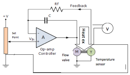
Figure 4. Closed loop electric diagram
Electronically, we could represent the simple closed-loop circuit using an operational amplifier (op-amp) for the controller, as the PID is composed of an operational amplifier with two sets of capacitor and resistance as input, one in parallel and the other one in series (figure below). The controller connected to the power supply, compares the set point against the process variable (temperature) and allows an output voltage to feed the flow valve which controls the temperature outside the heat exchanger. The console is represented as V and functions like and oscilloscope, graphing the process variable (temperature). Generally, the sequence is the same as the closed loop block diagram.
Desired process function
We can tune our PID in order to make the process behave as we need. From the desired values for the settling time (2τ) and the peak magnitude (15%), we obtain the parameters of the desired process function:

CONTROLLER FUNCTION
The PID controller function is:
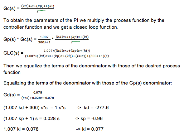
As the gains of the PID are negative, we assume that the pole placement method can't be applied in this case. Maybe another method could be useful to tune the PID controller, such as root locus.
PID CONTROLLER
The PID controller allows us to control the electro-pneumatic valve (final control element) according to the process variable. We can set it on manual (open loop) or automatic mode (closed loop). First we should connect the flow valve as the output using banana cables, and in order to get the temperature from the thermocouple, we should also connect this device as the input. If we want to work on automatic mode we can record the gains of the PID. We tried with the recommended values in the manual: kp = 60, kd = 0.03 and ki = 0.25. And we observed that a big overshoot was avoided and with this, our system was being protected.
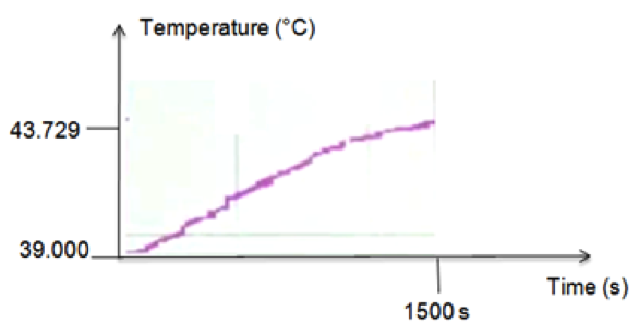
Figure 5. System response in closed loop
We built a system in simulink but with other values of the gains, just to demonstrate that we could simulate the behavior of the system with software.
The block STEP was found in the catalog “SOURCE” in the SIMULINK library. The block SUBSTRACT was found in the catalog “MATH OPERATIONS” as well as the gain. The block TRANSFER FCN was found in the catalog “CONTINUOUS” as well as the PID CONTROLLER, and the block SCOPE in “SINKS”.
Then, the SIMULINK diagram was created with these closed loop characteristics. The final graph obtained was:
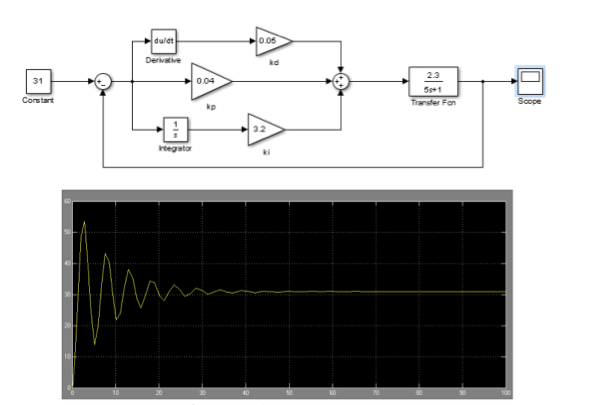
Figure 6. Simulation of the PID controller in simulink
With this we confirmed that we can use SIMULINK to find the gains of the PID controller that result in the desired behavior of our system.
Abbreviations used:
Abbreviations used:
- JI = damping ratio
- Wn = natural frequency
- ts = settling time
- Mp = peak magnitude
- Gd (s) = desired transfer function
- Gp (s) = Process transfer function
- Gc (s) = Controller transfer function
- G LC (s) = Closed loop controlled process transfer function
- kd = derivative gain
- kp = proportional gain
- ki = integral gain
